Ups and Downs, In and Outs and Longs and Shorts of Encoders
Oct 7, 2013There are many kinds of encoders and feedback devices. There are resolvers, encoders, glass scales, interferometer scales, inductive scales, capacitive scales, pulse coders, rotary-linear encoders, and even mechanical-hydraulic encoders. There are temperature specific scales and zero temperature scales. Each type of scale has its specific application and price. Also any type of scale can only perform at its best if installed, adjusted and maintained correctly.
As the senior technician of CMS’s metrology and calibration department I am sometimes called upon to figure out why “funny” things happen during positioning of an axis. This last week was a prime example.
What we will discuss this month is a very good example why CMS has invested heavily in technology and equipment to be able to solve even the most “funny” problems. In this instance I was called out to figure out why a B axis on a 5 axis machine was not positioning correctly. In this instance the customer was equipped with only a magnetic base and a dial indicator to confirm something was not right, and very correctly did.
The customer had a mishap with the machine. In this case the B axis was “bumped” quite firmly and the alignment was obviously not correct. The technician called onto the job was quite skilled and very knowledgeable in all things geometric. He very correctly tramed the B axis to be perpendicular with the Z axis and thought he was on his way to the soda pop machine. But alas, as a very skilled and diligent technician he knew it would behoove him to check the axis at +/- 90 degrees. He did this as skillful as an eagle snatching a salmon from the water. Unfortunately for him it seemed as if the eagle tried to swoop up a whale! The 90’s did not line up. Why not? The machine had just been laser aligned a month ago. What the heck? No soda for a bit.
At this point the signal went up and I was dispatched from the CMS Bat Cave. As swiftly as a turtle on his back I pointed the Sprinter West and put the hammer down. If you’re not aware, CMS has a Sprinter van as big as a house! If you thought the America’s Cup sail boats react to the wind, you should see how this rolling billboard gets blown around in a stiff breeze! Anyway, I made it there ASAP and got out the gear to see what’s up.
Below I will show the progression of the evaluation and explain what it means and also put some meaning to the title of this article.
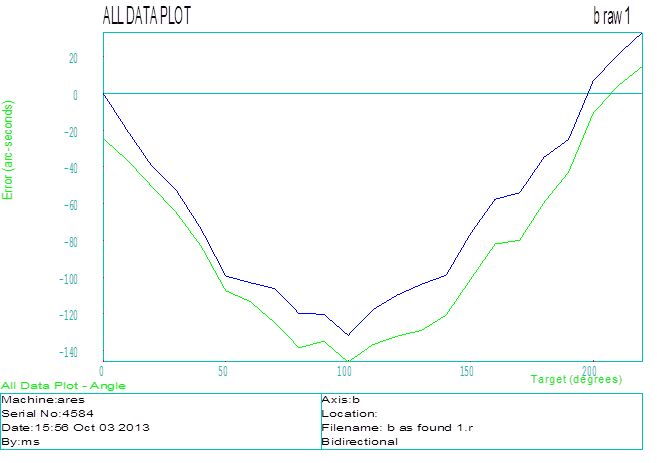
This is how the axis was found. The normal limits of this axis are usually less than 10 arc-seconds. In addition to this it’s not normal to see the axis be correct then off 140 arcs then return to correct. Do you know what’s wrong? … I do.
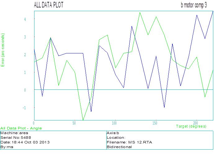
Below is the same axis with exactly the same set up and equipment 30 minutes later.
Before I break my arm patting myself on the back let me explain how darn small an arc-second is. If you had a tool that was 1 meter long, an arc-second would move the tip of that tool 4.84 microns. In empirical terms that would be 0.00019”. Even a silly long tool is 1/3rd that at 13” long and that would be 0.00006”, times my horrible 6 arc-seconds = 0.00036” at the tool tip. An average human hair is 0.003”. It’s 1/8th the diameter of a human hair at a foot. Not too bad. OK, enough of that.
Ins and outs, ups and downs, and longs and shorts do have some meaning here. This particular machine has a circular liner magnetic encoder. These encoders are very robust and accurate, but not very tolerant to misalignment. When I saw the top graph I knew we had an eccentricity problem with the encoder scale and the read head. When the magnetic lines of flux are crossed they rely on a consistent level of intensity. As the axis turned the intensity decreased then returned making the “funny” calibration table. I switched the machine to the rotary optical pulse coder inside the servo motor and recalibrated the axis. This is how and why CMS has the people and equipment it does to resolve problems quickly and correctly.
The ins and outs, ups and downs refer to the alignment. It must maintain lateral accuracy and a consistent air gap to perform to its expected longs and shorts of measurement. What had happened in this case was the “bump” of the B axis moved the gearbox of the B axis in the knuckle of the machine. The tape scale is mounted on the output flange of the gearbox. The reader head, which does not move, is mounted on the knuckle. This changed the relationship of the read head to the tape at different rotational positions causing inaccurate feedback positions.
Any questions or comments to this article please respond below.

